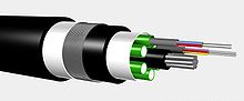
Optical fiber consists of a core and a cladding layer, selected for total internal reflection due to the difference in the refractive index between the two. In practical fibers, the cladding is usually coated with a layer of acrylate polymer or polyimide. This coating protects the fiber from damage but does not contribute to its optical waveguide properties. Individual coated fibers (or fibers formed into ribbons or bundles) then have a tough resin buffer layer and/or core tube(s) extruded around them to form the cable core. Several layers of protective sheathing, depending on the application, are added to form the cable. Rigid fiber assemblies sometimes put light-absorbing (“dark”) glass between the fibers, to prevent light that leaks out of one fiber from entering another. This reduces cross-talk between the fibers, or reduces flare in fiber bundle imaging applications.
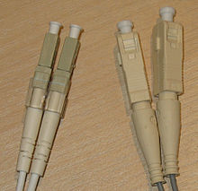
Left: LC/PC connectors
Right: SC/PC connectors
All four connectors have white caps covering the ferrules.
For indoor applications, the jacketed fiber is generally enclosed, with a bundle of flexible fibrous polymer strength members like aramid (e.g. Twaron or Kevlar), in a lightweight plastic cover to form a simple cable. Each end of the cable may be terminated with a specialized optical fiber connector to allow it to be easily connected and disconnected from transmitting and receiving equipment.
An optical fiber breakout cable
For use in more strenuous environments, a much more robust cable construction is required. In loose-tube construction the fiber is laid helically into semi-rigid tubes, allowing the cable to stretch without stretching the fiber itself. This protects the fiber from tension during laying and due to temperature changes. Loose-tube fiber may be “dry block” or gel-filled. Dry block offers less protection to the fibers than gel-filled, but costs considerably less. Instead of a loose tube, the fiber may be embedded in a heavy polymer jacket, commonly called “tight buffer” construction. Tight buffer cables are offered for a variety of applications, but the two most common are “Breakout” and “Distribution”. Breakout cables normally contain a ripcord, two non-conductive dielectric strengthening members (normally a glass rod epoxy), an aramid yarn, and 3 mm buffer tubing with an additional layer of Kevlar surrounding each fiber. The ripcord is a parallel cord of strong yarn that is situated under the jacket(s) of the cable for jacket removal. Distribution cables have an overall Kevlar wrapping, a ripcord, and a 900 micrometer buffer coating surrounding each fiber. These fiber units are commonly bundled with additional steel strength members, again with a helical twist to allow for stretching.
A critical concern in outdoor cabling is to protect the fiber from contamination by water. This is accomplished by use of solid barriers such as copper tubes, and water-repellent jelly or water-absorbing powder surrounding the fiber.
Modern cables come in a wide variety of sheathings and armor, designed for applications such as direct burial in trenches, dual use as power lines, installation in conduit, lashing to aerial telephone poles, submarine installation, and insertion in paved streets.
Patch cords
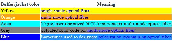
The buffer or jacket on patch cords is often color-coded to indicate the type of fiber used. The strain relief “boot” that protects the fiber from bending at a connector is color-coded to indicate the type of connection. Connectors with a plastic shell (such as SC connectors) typically use a color-coded shell. Standard color coding’s for jackets and boots (or connector shells) are shown below:
Multi-fiber cables
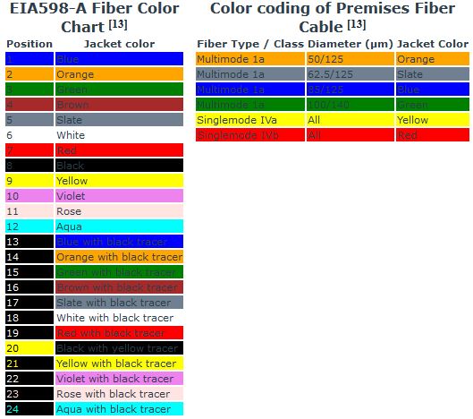
Individual fibers in a multi-fiber cable are often distinguished from one another by color-coded jackets or buffers on each fiber. The identification scheme used by Corning Cable Systems is based on EIA/TIA-598, “Optical Fiber Cable Color Coding.” EIA/TIA-598 defines identification schemes for fibers, buffered fibers, fiber units, and groups of fiber units within outside plant and premises optical fiber cables. This standard allows for fiber units to be identified by means of a printed legend. This method can be used for identification of fiber ribbons and fiber subunits. The legend will contain a corresponding printed numerical position number and/or color for use in identification.